3. Change settings
The Agent sends the data received from the Device Connector to the intdash server. During this process, the data can be filtered or resent depending on the status of the network.
The basic configuration is done in the manager configuration file (e.g. manager.conf).
To use Device Connectors, one configuration file is required for each Device Connector. The configuration file for the Device Connector to be used must be specified in the manager's configuration file.
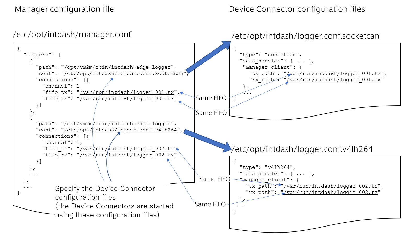
Fig. 1 Example of Manager configuration file and Device Connector configuration files
See All settings for Agent for a list of configurable items in the configuration file. Here are some typical configuration examples.
Note
The "logger" in the configuration file refers to the Device Connector.
3.1. Edge information setting
Set the edge account that the Agent uses to connect to intdash. Each client that communicates with the intdash server must be configured individually. As shown in the example below, specify the edge account UUID and the token in the settings of each client.
Note
Basically, use the same edge account for all clients of one Agent. In the example below, the Realtime and Resend clients use the same edge account.
Edge information setting example
{
  "clients": [
    {
      "my_id": "f90f2b42-66a5-4a57-8e99-468c36ebb6f2",                # (1)
      "my_secret": "sEh9ZHPoKX8QYU-v0Noe0ZPzxGBF..........................iBn5fn_eFM", # (2)
      "type": "realtime",
      ...
    },
    {
      "my_id": "f90f2b42-66a5-4a57-8e99-468c36ebb6f2",                # (1)
      "my_secret": "sEh9ZHPoKX8QYU-v0Noe0ZPzxGBF..........................iBn5fn_eFM", # (2)
      "type": "resend",
      ...
    }
  ],
  ...
}
Number |
Field |
Description |
|---|---|---|
(1) |
|
The edge UUID to assign to this client. |
(2) |
|
Client secret for authentication. |
Attention
Note when updating from a previous version of Edge Agent.
If you have updated from a version earlier than 1.19.0
Edge Agent version 1.19.0 and later uses an edge UUID and a client secret as authentication information. To use a client secret, you need to set
my_secretandauth_pathinclientsofmanager.conf.If you want to continue to use the configuration file
manager.conffrom Edge Agent 1.19.0 or earlier, refer to the configuration template/opt/vm2m/etc/manager.confand addmy_secretandauth_path. The value ofauth_pathshould be copied from the configuration template/opt/vm2m/etc/manager.conf.Note that authentication with edge tokens can still be used. If you want to use your edge token, set the edge token as
my_tokeninstead ofmy_secret. (The configuration filemanager.conffrom Edge Agent 1.19.0 and earlier can still be used.)
If you have updated from a version earlier than 1.24.0
Edge Agent version 1.24.0 or later allows you to specify a project to use. To specify a project, set
project_uuidinclientsof themanager.conffile.If you wish to continue to use the configuration file
manager.conffrom versions prior to Edge Agent 1.24.0, please refer to the configuration file template/opt/vm2m/etc/manager.confand addproject_uuid.Note that if a project UUID is not set, Global Project will be used. Global Project is a special project accessible to all users and edges within the intdash domain.
3.2. Settings for using the pre-installed Device Connector
Settings are required to use the pre-installed Device Connector intdash-edge-logger.
To configure the Device Connector, configure both the manager's configuration file (manager.conf) and the Device Connector's configuration file.
By preparing a configuration file for each Device Connector and setting multiple Device Connectors in the manager's configuration file, you can launch intdash-edge-logger in multiple processes to collect data from multiple devices.
Note
Acquiring video data from a camera
There are three ways to acquire video data using the pre-installed Device Connectors.
Acquire video from a camera that can output Motion JPEG and use an mjpeg-type Device Connector.
Acquire video from a camera that can output H.264 and use a v4lh264-type Device Connector.
Acquire H.264 output from GStreamer, using a Device Connector of type gstreamer_h264 (e.g., when converting RAW data from a camera to H.264 using GStreamer and then acquiring the converted data).
Choose an appropriate method according to the data format of your camera output.
The data format can be checked by installing the v4l2-ctl command.
The following command lists the formats that the camera device /dev/video0 can output.
$ v4l2-ctl -d /dev/video0 --list-formats
You can also check the resolution and frame rate that the camera can output with the following command.
$ v4l2-ctl -d /dev/video0 --list-formats-ext
3.2.1. Manager configuration file example (manager.conf)
In the manager's configuration file, fill in the Device Connector settings in loggers.
{
  "loggers": [
    {                                                   # (1)
      "path": "/opt/vm2m/sbin/intdash-edge-logger",     # (2)
      "conf": "/etc/opt/intdash/logger.conf.mjpeg",     # (3)
      "connections": [{
        "channel": 1,                                   # (4)
        "fifo_tx": "/var/run/intdash/logger_001.tx",    # (5)
        "fifo_rx": "/var/run/intdash/logger_001.rx"     # (6)
      }]
    },
    {                                                   # (7)
      "path": "/opt/vm2m/sbin/intdash-edge-logger",
      "conf": "/etc/opt/intdash/logger.conf.nmea",
      "connections": [{
        "channel": 2,
        "fifo_tx": "/var/run/intdash/logger_002.tx",
        "fifo_rx": "/var/run/intdash/logger_002.rx"
      }]
    },
    ...
  ],
  ...
}
Number |
Field |
Description |
|---|---|---|
(1) |
- |
The connection with one Device Connector is represented by one JSON object. |
(2) |
|
Full path of the pre-installed Device Connector. |
(3) |
|
The configuration file for the Device Connector. Here, the setting |
(4) |
|
The channel (0-255) to be used for this Device Connector. A channel number is assigned to the data obtained from the Device Connector. The channel number should not be duplicated with other Device Connectors. |
(5) |
|
The FIFO path that this Device Connector uses to send data. The path should not overlap with other Device Connectors. |
(6) |
|
The FIFO path that this Device Connector uses to receive data. The path should not overlap with other Device Connectors. |
(7) |
- |
If you want to use more than one Device Connector, configure the second Device Connector from here. Make the settings in the same way as above. |
3.2.2. Device connector configuration file example
3.2.2.1. Setting example of mjpeg type Device Connector
The mjpeg type Device Connector acquires Motion JPEG data from a UVC (USB Video Class) camera that supports Video4Linux. Therefore, the camera needs to be able to output Motion JPEG.
Configuration file /etc/opt/intdash/logger.conf.mjpeg
{
  "type": "mjpeg",                                 # (1)
  "data_handler": {
    "path": "/dev/video0",                         # (2)
    "baudrate": 15,                                # (3)
    "camera_width": 320,                           # (4)
    "camera_height": 240,                          # (5)
    "camera_hwencodedelay_msec": 100               # (6)
  },
  "manager_client": {
    "tx_path": "/var/run/intdash/logger_XXX.tx",   # (7)
    "rx_path": "/var/run/intdash/logger_XXX.rx"    # (8)
  },
  "basetime": "/var/run/intdash/basetime",         # (9)
  "status": "/var/run/intdash/logger_XXX.stat"     # (10)
}
Number |
Field |
Description |
|---|---|---|
(1) |
|
The type of the Device Connector. For mjpeg type, use "mjpeg". |
(2) |
|
Device path |
(3) |
|
Frame rate [fps]. Set the combination of frame rate, frame width, and frame height that the camera supports. |
(4) |
|
Frame width |
(5) |
|
Frame height |
(6) |
|
Timestamp offset (camera processing time) [msec]. For example, if you set |
(7) |
|
The FIFO path used by the Device Connector to send data. Set the same path as the fifo_tx for this Device Connector in manager.conf. |
(8) |
|
The FIFO path used by the Device Connector to receive data. Set the same path as the fifo_rx for this Device Connector in manager.conf. |
(9) |
|
The path to the file that the Device Connector uses for time management. Set the same value as manager.basetime in manager.conf. |
(10) |
|
The path to the file that the Device Connector writes the status to. |
3.2.2.2. Setting example of v4lh264 type Device Connector
The v4lh264 type Device Connector acquires H.264 data from a UVC (USB Video Class) camera that supports Video4Linux. Therefore, the camera needs to be able to output H.264.
Configuration file /etc/opt/intdash/logger.conf.v4lh264
{
 "type": "v4lh264",                               # (1)
 "data_handler": {
   "path": "/dev/video0",                         # (2)
   "baudrate": 15,                                # (3)
   "camera_width": 1920,                          # (4)
   "camera_height": 1080,                         # (5)
   "camera_hwencodedelay_msec": 100               # (6)
 },
 "manager_client": {
   "tx_path": "/var/run/intdash/logger_XXX.tx",   # (7)
   "rx_path": "/var/run/intdash/logger_XXX.rx"    # (8)
 },
 "basetime": "/var/run/intdash/basetime",         # (9)
 "status": "/var/run/intdash/logger_XXX.stat"     # (10)
}
Number |
Field |
Description |
|---|---|---|
(1) |
|
The type of Device Connector. For v4lh264 type, set to "v4lh264". |
(2) |
|
Device path |
(3) |
|
Frame rate [fps]. Set the combination of frame rate, frame width, and frame height that the camera supports. |
(4) |
|
Frame width |
(5) |
|
Frame height |
(6) |
|
Timestamp offset (camera processing time) [msec]. For example, if you set |
(7) |
|
The FIFO path used by the Device Connector to send data. Set the same path as the fifo_tx for this Device Connector in manager.conf. |
(8) |
|
The FIFO path used by the Device Connector to receive data. Set the same path as the fifo_rx for this Device Connector in manager.conf. |
(9) |
|
The path to the file that the Device Connector uses for time management. Set the same value as manager.basetime in manager.conf. |
(10) |
|
The path to the file that the pre-installed Device Connector writes the status to. |
3.2.2.3. Example setting of gstreamer_h264 type Device Connector
The gstreamer_h264 type Device Connector acquires H.264 video from GStreamer. Therefore, GStreamer needs to output H.264.
Configuration file /etc/opt/intdash/logger.conf.gstreamer_h264
This example uses VA-API (Video Acceleration API), so it can only be used with hardware that supports VA-API.
{
 "type": "gstreamer_h264",                        # (1)
 "data_handler": {
   "path": "/dev/video0",                         # (2)
   "baudrate": 15,                                # (3)
   "camera_width": 1920,                          # (4)
   "camera_height": 1080,                         # (5)
   "camera_keyperiod": 150,                       # (6)
   "camera_hwencodedelay_msec": 100,              # (7)
   "command": "gst-launch-1.0 -q v4l2src device=$_PATH ! image/jpeg,width=$_WIDTH,height=$_HEIGHT,framerate=$_FPS/1 ! queue ! vaapijpegdec ! queue ! vaapipostproc ! queue ! vaapih264enc rate-control=1 bitrate=3072 max-bframes=0 keyframe-period=$_KEYPERIOD ! fdsink fd=1" # (8)
 },
 "manager_client": {
   "tx_path": "/var/run/intdash/logger_XXX.tx",   # (9)
   "rx_path": "/var/run/intdash/logger_XXX.rx"    # (10)
 },
 "basetime": "/var/run/intdash/basetime",         # (11)
 "status": "/var/run/intdash/logger_XXX.stat"     # (12)
}
Number |
Field |
Description |
|---|---|---|
(1) |
|
The type of Device Connector. For gstreamer_h264 type, set to "gstreamer_h264". |
(2) |
|
Device path |
(3) |
|
Frame rate [fps]. The value set here is only used as the variable |
(4) |
|
Frame width. The value set here is only used as the variable |
(5) |
|
Frame height. The value set here is only used as the variable |
(6) |
|
Keyframe interval (set frame rate x 10) |
(7) |
|
Timestamp offset (camera processing time) [msec]. For example, if you set |
(8) |
|
GStreamer command. Set the pipeline suitable for the camera and the runtime system so that H.264 data is output from the standard output of the command. |
(9) |
|
The FIFO path used by the Device Connector to send data. Set the same path as the fifo_tx for this Device Connector in manager.conf. |
(10) |
|
The FIFO path used by the Device Connector to receive data. Set the same path as the fifo_rx for this Device Connector in manager.conf. |
(11) |
|
The path to the file that the Device Connector uses for time management. Set the same value as manager.basetime in manager.conf. |
(12) |
|
The path to the file that the pre-installed Device Connector writes the status to. |
In the command, other setting values can be referred to by using the following variables.
- $_PATH
The value set for
path- $_FPS
The value set to
baudrate- $_WIDTH
The value set to
camera_width- $_HEIGHT
The value set to
camera_height- $_KEYPERIOD
The value set to
camera_keyperiod
3.2.2.4. Setting example of nmea type Device Connector
nmea type Device Connector acquires NMEA data from GPS device
Configuration file /etc/opt/intdash/logger.conf.nmea
{
 "type": "nmea",                                  # (1)
 "data_handler": {
   "path": "/dev/ttyXX",                          # (2)
   "baudrate": 57600                              # (3)
 },
 "manager_client": {
   "tx_path": "/var/run/intdash/logger_XXX.tx",   # (4)
   "rx_path": "/var/run/intdash/logger_XXX.rx"    # (5)
 },
 "basetime": "/var/run/intdash/basetime",         # (6)
 "status": "/var/run/intdash/logger_XXX.stat"     # (7)
}
Number |
Field |
Description |
|---|---|---|
(1) |
|
The type of Device Connector. For nmea type, set to "nmea". |
(2) |
|
Device path |
(3) |
|
Communication baud rate with GPS module [bps] |
(4) |
|
The FIFO path used by the Device Connector to send data. Set the same path as the fifo_tx for this Device Connector in manager.conf. |
(5) |
|
The FIFO path used by the Device Connector to receive data. Set the same path as the fifo_rx for this Device Connector in manager.conf. |
(6) |
|
The path to the file that the Device Connector uses for time management. Set the same value as manager.basetime in manager.conf. |
(7) |
|
The path to the file that the pre-installed Device Connector writes the status to. |
3.2.2.5. Setting example of socketcan type Device Connector
A socketcan type Device Connector gets CAN data from the open source SocketCAN driver.
Configuration file /etc/opt/intdash/logger.conf.socketcan
{
  "type": "socketcan",                             # (1)
  "data_handler": {
    "path": "can0",                                # (2)
    "baudrate": 500,                               # (3)
    "listenonly": 0                                # (4)
  },
  "manager_client": {
    "tx_path": "/var/run/intdash/logger_XXX.tx",   # (5)
    "rx_path": "/var/run/intdash/logger_XXX.rx"    # (6)
  },
  "basetime": "/var/run/intdash/basetime",         # (7)
  "status": "/var/run/intdash/logger_XXX.stat"     # (8)
}
Number |
Field |
Description |
|---|---|---|
(1) |
|
The type of Device Connector. For socketcan type, set to "socketcan". |
(2) |
|
Interface name |
(3) |
|
CAN bus baud rate (125, 250, 500, 1000) [Kbps] |
(4) |
|
(int) 0: returns ACK, non-zero: does not return ACK |
(5) |
|
The FIFO path used by the Device Connector to send data. Set the same path as the fifo_tx for this Device Connector in manager.conf. |
(6) |
|
The FIFO path used by the Device Connector to receive data. Set the same path as the fifo_rx for this Device Connector in manager.conf. |
(7) |
|
The path to the file that the Device Connector uses for time management. Set the same value as manager.basetime in manager.conf. |
(8) |
|
The path to the file that the pre-installed Device Connector writes the status to. |
3.2.2.6. Setting example of canopen type Device Connector
A canopen type Device Connector acquires CANOpen data from the open source SocketCAN driver.
Configuration file /etc/opt/intdash/logger.conf.canopen
{
  "type": "canopen",                               # (1)
  "data_handler": {
    "path": "can0",                                # (2)
    "baudrate": 500,                               # (3)
    "listenonly": 0                                # (4)
  },
  "manager_client": {
    "tx_path": "/var/run/intdash/logger_XXX.tx",   # (5)
    "rx_path": "/var/run/intdash/logger_XXX.rx"    # (6)
  },
  "basetime": "/var/run/intdash/basetime",         # (7)
  "status": "/var/run/intdash/logger_XXX.stat"     # (8)
}
Number |
Field |
Description |
|---|---|---|
(1) |
|
The type of Device Connector. For canopen type, set to "canopen". |
(2) |
|
Interface name |
(3) |
|
CAN bus baud rate (125, 250, 500, 1000) [Kbps] |
(4) |
|
(int) 0: returns ACK, non-zero: does not return ACK |
(5) |
|
The FIFO path used by the Device Connector to send data. Set the same path as the fifo_tx for this Device Connector in manager.conf. |
(6) |
|
The FIFO path used by the Device Connector to receive data. Set the same path as the fifo_rx for this Device Connector in manager.conf. |
(7) |
|
The path to the file that the Device Connector uses for time management. Set the same value as manager.basetime in manager.conf. |
(8) |
|
The path to the file that the pre-installed Device Connector writes the status to. |
3.3. Settings related to sending and receiving of data
The Agent can receive data from the intdash server and send it to the Device Connector.
The following is an example of settings for sending and receiving data between two agents.
3.3.1. Setting example for sending and receiving CAN data (destination is not specified)
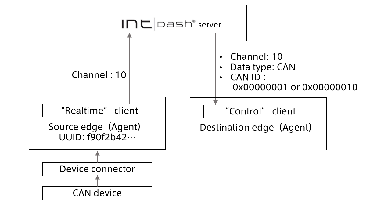
The following example is a configuration for an Agent to send CAN data to another Agent via the intdash server.
In this configuration example, the receiving Agent receives the CAN data sent by the sending Agent on channel 10.
3.3.1.1. Setting example of CAN data sender edge (destination is not specified)
{
  "clients": [{
    ...
    "my_id": "f90f2b42-66a5-4a57-8e99-468c36ebb6f2",                # (1)
    "my_secret": "sEh9ZHPoKX8QYU-v0Noe0ZPzxGBF..........................iBn5fn_eFM", # (2)
    "type": "realtime",                                             # (3)
    ...
  }],
  "loggers": [{                                                     # (4)
    "connections": [{
        "channel": 10,                                              # (5)
        ...
    }],
    ...
  }],
  ...
}
Number |
Field |
Description |
|---|---|---|
(1) |
|
UUID of the sending edge (this edge) |
(2) |
|
Client secret for the sending edge (this edge). Reference: Edge information setting. |
(3) |
|
The Realtime client |
(4) |
|
Set the Device Connector that acquires CAN data. |
(5) |
|
The channel to send data. |
3.3.1.2. Setting example of CAN data receiving edge
{
  "clients": [{
    ...
    "protocol": "mod_websocket.v2",                                 # (1)
    "my_id": "c35618bf-aa2c-4abc-8a4e-5b157b90c9ef",                # (2)
    "my_secret": "hsNxJhvDNHR2QcXbXl..........................Z0RWKvfPs_neAkjTNSO5", # (3)
    "down_dst_id": "00000000-0000-0000-0000-000000000000",          # (4)
    "ctlr_id": "f90f2b42-66a5-4a57-8e99-468c36ebb6f2",              # (5)
    "ctlr_flts":[                                                   # (6)
      {
        "channel": 10,                                              # (7)
        "dtype": 1,                                                 # (8)
        "ids": [1, 16]                                              # (9)
      }
    ],
    "type": "control",                                              # (10)
    "connection": {
      "path": "/api/v1/ws/measurements",                            # (11)
      ...
    },
    ...
  }],
  "loggers": [{
    "connections": [{
        "channel": 10,                                              # (12)
        ...
    }],
    ...
  }],
  ...
}
Number |
Field |
Description |
|---|---|---|
(1) |
|
If you use the Control client, specify |
(2) |
|
UUID of the receiving edge (this edge) |
(3) |
|
Client secret for the receiving edge (this edge). Reference: Edge information setting. |
(4) |
|
Data addressed to the UUID specified here is received. If |
(5) |
|
UUID of the source edge of the data to be received (only the data sent from the specified edge is received) |
(6) |
|
A filter that specifies the data to receive. Specify by the combination of channel, iSCP data type, and ID. Multiple filters can be set (allow list). (You can filter the data received from the intdash server. For more information on filtering data to be received, refer to the iSCP 1.0 documentation.) |
(7) |
|
Channel of data to receive (In this example, only the data of channel 10 is received.) |
(8) |
|
The type of data to receive. Specify the iSCP data type code in decimal notation. (In this case, 1 represents CAN. Only CAN data is received.) |
(9) |
|
CAN ID of the data to be received (This example shows that only the data whose CAN ID is |
(10) |
|
Use the Control client ( |
(11) |
|
If you use the Control client, specify |
(12) |
|
The channel on which the Device Connector receives data. In this example, this edge uses channel 10. |
Note
To receive data from two edges, use ctlr_ids instead of ctlr_id. It is not possible to receive data from three or more edges.
Important
In the dtype field, specify the iSCP data type code in decimal notation. The iSCP data type codes are as follows.
Data type code (decimal) |
Data type |
|---|---|
0x01 (1) |
CAN |
0x02 (2) |
NMEA |
0x03 (3) |
General Sensor |
0x04 (4) |
Controlpad |
0x05 (5) |
MAVLink 1 Packet (Communication protocol for Micro Air Vehicles/drones) |
0x09 (9) |
JPEG |
0x0A (10) |
String |
0x0B (11) |
Float (Double precision floating point number) |
0x0C (12) |
Int (64bit signed integer) |
0x0D (13) |
H.264 |
0x0E (14) |
Bytes (Byte sequence) |
0x0F (15) |
PCM(WAVE) |
0x10 (16) |
AAC(ADTS) |
0x7F (127) |
Generic (Generic binary data) |
Note that the above data type codes for iSCP are different from the data type codes for FIFO data format used between Agent and Device Connector.
3.4. Settings for sending timing (filtering on the sender's side)
By setting a filter on the sending agent, you can distribute the data to the Realtime client or Bulk client that sends the data to the intdash server, and adjust the data transmission timing. For more information on filters, see Filter at the sender's side.
3.4.1. A setting example in which low frequency data is sent in real time and the rest of the data is sent later.
If the network bandwidth is narrow, sampling can be used to thin out the data so that only some data can be sent by the Realtime client and the rest of the data can be sent by the Resend client when the bandwidth is restored.
A setting example where channel 1 is sampled at 1-second intervals, the sampled data is sent by the Realtime client, and the rest of the data is sent by the Resend client
{
  "manager": {
    "filters": [
      {
        "name": "sampling",                                           # (1)
        "channel": "1",                                               # (2)
        "target": "realtime",                                         # (3)
        "setting": [
          {
            "key": "rate",                                            # (4)
            "value": "1000"                                           # (5)
          }
        ]
      }
    ],
    ...
  },
  "clients": [
    {
      "my_id": "f90f2b42-66a5-4a57-8e99-468c36ebb6f2",                # (6)
      "my_secret": "sEh9ZHPoKX8QYU-v0Noe0ZPzxGBF...........................iBn5fn_eFM", # (7)
      "type": "realtime",                                             # (8)
      "protocol": "mod_websocket.v2",                                 # (9)
      ...
    },
    {
      "my_id": "f90f2b42-66a5-4a57-8e99-468c36ebb6f2",                # (6)
      "my_secret": "sEh9ZHPoKX8QYU-v0Noe0ZPzxGBF...........................iBn5fn_eFM", # (7)
      "type": "bulk",                                                 # (10)
      "protocol": "mod_websocket.v2",                                 # (9)
      "store_cycle": 0,                                               # (11)
      ...
    },
    {
      "my_id": "f90f2b42-66a5-4a57-8e99-468c36ebb6f2",                # (6)
      "my_secret": "sEh9ZHPoKX8QYU-v0Noe0ZPzxGBF...........................iBn5fn_eFM", # (7)
      "type": "resend",                                               # (12)
      "protocol": "mod_http",                                         # (13)
      ...
    }
  ],
  "loggers": [{
    "connections": [{
        "channel": 1,                                                 # (14)
        ...
    }],
    ...
  }],
  ...
}
Number |
Field |
Description |
|---|---|---|
(1) |
|
The type of filter, |
(2) |
|
The channel to be filtered. In this example, channel 1 is set. |
(3) |
|
How to send the filtered content. Set to |
(4) |
|
Advanced filter settings. Use |
(5) |
|
Advanced filter settings. In this example, the sampling period is set to 1000 milliseconds (1 second). Therefore, this edge sends one piece of data per second. |
(6) |
|
The UUID of the sending edge (this edge). |
(7) |
|
Client secret for the sending edge (this edge). Reference: Edge information setting. |
(8) |
|
Sending client type, |
(9) |
|
Communication protocol of the sending client. Specify |
(10) |
|
Sending client type, |
(11) |
|
Sending interval for the Bulk client. Set this to 0 to delegate data transmission to the Resend client. |
(12) |
|
Sending client type, |
(13) |
|
Communication protocol of the sending client. In this example, the Resend client uses the REST API, so specify |
(14) |
|
The channel to be used for the acquired data. In this example, this Device Connector (logger) is channel 1. |
3.4.2. Setting example to send some data in real time and send other data later
If network bandwidth is tight, you can configure the Realtime client to send only small or infrequent data and the rest of the data to be sent by the Resend client when the bandwidth is restored.
Setting example for sending data other than channel 1 with the Realtime client and delegate the channel 1 data to the Resend client
{
  "manager": {
    "filters": [
      {
        "name": "channel",                                            # (1)
        "channel": "1",                                               # (2)
        "target": "realtime",                                         # (3)
        "setting": []                                                 # (4)
      }
    ],
    ...
  },
  "clients": [
    {
      "my_id": "f90f2b42-66a5-4a57-8e99-468c36ebb6f2",                # (5)
      "my_secret": "sEh9ZHPoKX8QYU-v0Noe0ZPzxGBF...........................iBn5fn_eFM", # (6)
      "type": "realtime",                                             # (7)
      "protocol": "mod_websocket.v2",                                 # (8)
      ...
    },
    {
      "my_id": "f90f2b42-66a5-4a57-8e99-468c36ebb6f2",                # (5)
      "my_secret": "sEh9ZHPoKX8QYU-v0Noe0ZPzxGBF...........................iBn5fn_eFM", # (6)
      "type": "bulk",                                                 # (9)
      "protocol": "mod_websocket.v2",                                 # (8)
      "store_cycle": 0,                                               # (10)
      ...
    },
    {
      "my_id": "f90f2b42-66a5-4a57-8e99-468c36ebb6f2",                # (5)
      "my_secret": "sEh9ZHPoKX8QYU-v0Noe0ZPzxGBF...........................iBn5fn_eFM", # (6)
      "type": "resend",                                               # (11)
      "protocol": "mod_http",                                         # (12)
      ...
    }
  ],
  "loggers": [
    {
      "connections": [{
          "channel": 1,                                                 # (13)
          ...
      }],
      ...
    },
    {
      "connections": [{
          "channel": 2,                                                 # (14)
          ...
      }],
      ...
    }
  ],
  ...
}
Number |
Field |
Description |
|---|---|---|
(1) |
|
The type of filter, |
(2) |
|
The channel to be filtered. In this example, it is channel 1. |
(3) |
|
How to send the filtered content. Set to |
(4) |
|
Advanced filter settings. Leave the settings empty. |
(5) |
|
The UUID of the sending edge (this edge). |
(6) |
|
Client secret for the sending edge (this edge). Reference: Edge information setting. |
(7) |
|
Sending client type, |
(8) |
|
Communication protocol of the sending client. Specify |
(9) |
|
Sending client type, |
(10) |
|
Sending interval of the Bulk client. Set this to 0 to delegate data transmission to the Resend client. |
(11) |
|
Sending client type, |
(12) |
|
Communication protocol of the sending client. In this example, the Resend client uses the REST API, so specify |
(13) |
|
Channel to be assigned to the acquired data. In this example, the first Device Connector (logger) is channel 1. |
(14) |
|
Channel to be assigned to the acquired data. In this example, the second Device Connector (logger) is channel 2. |
3.4.3. Setting example to save all data as RAW data without sending
If there is no network connection or the bandwidth is too narrow to send data, you can give up sending data to the intdash server and dump all the data to your local storage. The data dumped to the local storage will need to be manually uploaded to the intdash server later.
Setting example not to send data to the server
{
  "manager": {
    ...
  },
  "clients": [],                                                        # (1)
  "loggers": [
    {
      "connections": [{
          "channel": 1,                                                 # (2)
          ...
      }],
      ...
    },
    {
      "connections": [{
          "channel": 2,                                                 # (3)
          ...
      }],
      ...
    }
  ],
  ...
}
Number |
Field |
Description |
|---|---|---|
(1) |
|
Client settings. Leave the sending client settings empty. |
(2) |
|
Channel to be assigned to the acquired data. In this example, the first Device Connector (logger) is channel 1. |
(3) |
|
Channel to be assigned to the acquired data. In this example, the second Device Connector (logger) is channel 2. |
3.4.4. Setting example to store all data for Resend client
If the network is unstable and the bandwidth fluctuates greatly, you can give up the real-time transmission, store all the data, and send with the Resend client in one batch when the bandwidth is restored. This retransmission process by the Resend client is automatic and you do not need to manually upload the data to the intdash server.
Setting example to delegate the data of all channels to the Resend client without sending in real time
{
  "manager": {
    "filters": [
      {
        "name": "channel",                                            # (1)
        "channel": "-1",                                              # (2)
        "target": "realtime",                                         # (3)
        "setting": []                                                 # (4)
      }
    ],
    ...
  },
  "clients": [
    {
      "my_id": "f90f2b42-66a5-4a57-8e99-468c36ebb6f2",                # (5)
      "my_secret": "sEh9ZHPoKX8QYU-v0Noe0ZPzxGBF...........................iBn5fn_eFM", # (6)
      "type": "realtime",                                             # (7)
      "protocol": "mod_websocket.v2",                                 # (8)
      ...
    },
    {
      "my_id": "f90f2b42-66a5-4a57-8e99-468c36ebb6f2",                # (5)
      "my_secret": "sEh9ZHPoKX8QYU-v0Noe0ZPzxGBF...........................iBn5fn_eFM", # (6)
      "type": "bulk",                                                 # (9)
      "protocol": "mod_websocket.v2",                                 # (8)
      "store_cycle": 0,                                               # (10)
      ...
    },
    {
      "my_id": "f90f2b42-66a5-4a57-8e99-468c36ebb6f2",                # (5)
      "my_secret": "sEh9ZHPoKX8QYU-v0Noe0ZPzxGBF...........................iBn5fn_eFM", # (6)
      "type": "resend",                                               # (11)
      "protocol": "mod_http",                                         # (12)
      ...
    }
  ],
  "loggers": [
    {
      "connections": [{
          "channel": 1,                                                 # (13)
          ...
      }],
      ...
    },
    {
      "connections": [{
          "channel": 2,                                                 # (14)
          ...
      }],
      ...
    }
  ],
  ...
}
Number |
Field |
Description |
|---|---|---|
(1) |
|
The type of filter, |
(2) |
|
The channel to be filtered. Set to "-1" which means that all channels are filtered. |
(3) |
|
How to send the filtered content. Set to |
(4) |
|
Advanced filter settings. Leave the settings empty. |
(5) |
|
The UUID of the sending edge (this edge). |
(6) |
|
Client secret for the sending edge (this edge). Reference: Edge information setting. |
(7) |
|
Sending client type, |
(8) |
|
Communication protocol of the sending client. Specify |
(9) |
|
Sending client type, |
(10) |
|
Sending interval of the Bulk client. Set this to 0 to delegate data transmission to the Resend client. |
(11) |
|
Sending client type, |
(12) |
|
Communication protocol of the sending client. In this example, the Resend client uses the REST API, so specify |
(13) |
|
The channel to be used for the acquired data. In this example, this Device Connector (logger) is channel 1. |
(14) |
|
Channel to be assigned to the acquired data. In this example, this Device Connector (logger) is channel 2. |
3.5. Settings related to saving RAW data
For more information on RAW data, see RAW data.
The following settings can be made for RAW data.
3.5.1. Preventing any data from being saved as RAW data
To prevent any data from being saved as RAW data, set manager.rawdir to null.
Example (No RAW data saved):
{
  "manager": {
    ...
    "rawdir": null,
    ...
  },
  ...
}
3.5.2. Preventing the storage of RAW data for a specific channel
Add loggers[].connections[].disable_raw to the Device Connector settings and set the value to 1.
Example (Disabling RAW data storage for channel 0):
{
  "loggers": [{
    "connections": [{
      ...
      "disable_raw": 1,
      "channel": 0,
      ...
    }],
    ...
  }],
  ...
}