7. Acquire data from devices (Device Connectors)#
Terminal System v1.23.0
The Device Connector is software that receives data from devices connected to the Terminal System (CAN-USB Interface, cameras, GPS devices, etc.).
The device connector must be configured for each device to be used.
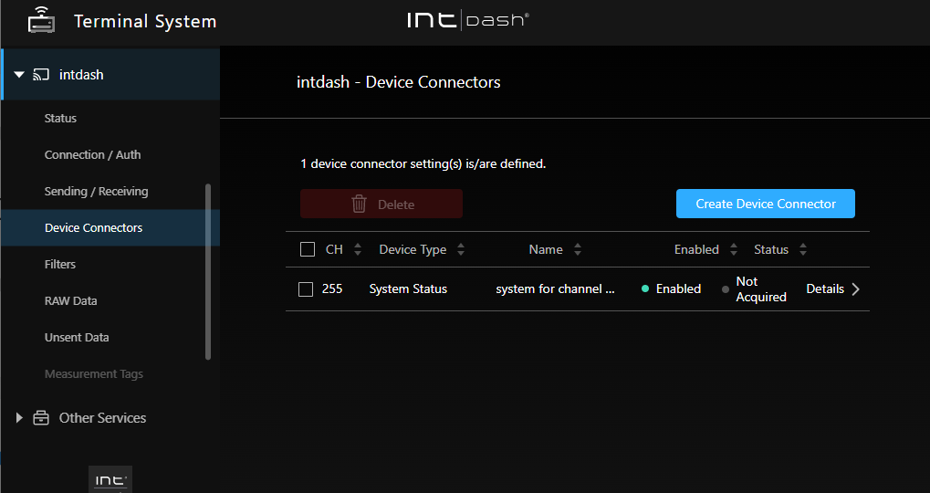
Fig. 70 [intdash] menu > [Device Connectors].#
7.1. Create/modify new device connector settings#
Attention
To create device connector settings, the Terminal System must already have recognized the device. With the device connected, power on the Terminal System.
To create device connector settings, go to the [intdash] menu > [Device Connectors] and click [Create Device Connector]. To change the settings of an existing device connector, click [Details].
In the device connector settings, configure the following.
- CH
A channel number used for data identification; the Terminal System does not allow multiple device connectors to be created with the same channel number.
- Device Type
Select the device type. For more information about device types, see Available device types and configuration items. (You cannot change the device type of an existing device connector setting.)
- Name
You can give the device connector an arbitrary name.
- Enabled
Turn on the device connector you want to use.
- Status
The status of the device connector is displayed.
Connected: Device connector is working properly.
Not Acquired/No Data/Disconnected: The connection to the device has not been established. Check the connection to the device and the cable. If the device itself has a status indicator (e.g. LED), check if the status indicator is normal.
Error: Check the contents of the error message and try to resolve the error. If the problem persists, please contact our support desk.
After configuring the settings, click [Save Changes].
If a message appears at the top of the screen requesting a restart, the settings will take effect after the restart. If you click [Restart] in the [intdash] menu > [Status], the intdash service will be started with the new settings and the measurement will begin.
7.2. Available device types and configuration items#
The available device types and configuration items are as follows.
Note
If you want to use your own device connector, select the device type [Custom]. For information on how to develop device connectors, see the intdash Edge Agent Developer Guide for details on how to develop device connectors.
7.2.1. ANALOG-USB Interface#
This is the device connector for using the EDGEPLANT ANALOG-USB Interface EP1-AG08A made by aptpod.
- Analog Input Sampling Frequency
Specify the sampling frequency (common to all ports of ANALOG-USB Interface).
- Analog Input Ch (number) Enabled
Enables/Disables each analog input port of ANALOG-USB Interface.
- Analog Input Ch (number) Voltage
Specify the range of input voltage for each analog input port of ANALOG-USB Interface.
- Analog Output Enabled
Turn on if you want to use the analog output port of ANALOG-USB Interface.
- Analog Output Waveform
Select a signal waveform to output from the analog output port of ANALOG-USB Interface (0: pseudo-random signal, 1: sine wave, 2: triangle wave, 3: square wave, 16: fixed signal).
- Analog Output Voltage
Specify the voltage of the signal to be output from the analog output port of ANALOG-USB Interface.
- Analog Output Frequency
Specify the frequency of the signal waveform to be output from the analog output port of ANALOG-USB Interface.
- Timestamp Mode
Sets how the timestamp is given to the received data.
device: Timestamps are given using the clock of the ANALOG-USB Interface. It is more accurate thanhosttimestamps.host: Timestamps are given using the clock of the Terminal System computer.
If you want to synchronize multiple aptpod USB interfaces using a sync cable, select
devicein each device connector setting.However, if you select
devicehere, there may be a time difference between the aptpod USB interface and other devices. This is because devices other than aptpod USB interface use the clock of the Terminal System computer (equivalent tohost).If time synchronization between aptpod USB interfaces and other devices is important, select
hostfor the aptpod USB interface to use the clock of the Terminal System computer.- Device Path
Select the device path of the connected ANALOG-USB Interface. Multiple device connectors cannot use the same device path.
7.2.2. Audio#
This is the device connector used to acquire audio data.
- Format
Select the audio data format (S16LE: signed 16 bit little-endian, S32LE: signed 32 bit little-endian, F32LE: floating-point little-endian).
- Sampling Frequency
Enter a numerical value. (Unit: Hz)
- Number of Channels
Enter the number of channels.
- Device Path
Select the device path of the connected ANALOG-USB Interface. Multiple device connectors cannot use the same device path.
- Mic Jack Audio Element
If you use the computer's microphone jack, enter the name of the device element that indicates the status (plugged or unplugged) of the microphone jack.
When using the VTC 1910-S as a Terminal System computer:
Mic Jack.When using the EDGEPLANT T1 as your Terminal System computer:
y Jack-state.
- Interface
Enter the type of audio control device.
When using the VTC 1910-S as a Terminal System computer:
CARDWhen using the EDGEPLANT T1 as your Terminal System computer:
MIXER
- Command
Enter a GStreamer command. Set up the appropriate pipeline for the audio input you are using, and make sure that the audio data is output from the GStreamer's standard output.
The following variables can be used in the command to refer to other setting values.
Variables
Values
$_DEVICEFull path set in [Device Path].
$_FORMATThe value set for [Format].
$_RATEThe value set for [Sampling Frequency].
$_CHANNELSThe value set for [Number of Channels].
Command example when using the VTC 1910-S as the Terminal System computer:
gst-launch-1.0 -q alsasrc device=$_DEVICE ! audioconvert ! audio/x-raw,format=$_FORMAT,rate=$_RATE,channels=$_CHANNELS ! fdsink fd=1
Command example when using the EDGEPLANT T1 as the Terminal System computer:
gst-launch-1.0 -q alsasrc device=hw:1 ! audioconvert ! audio/x-raw,format=$_FORMAT,rate=$_RATE,channels=$_CHANNELS ! fdsink fd=1
7.2.3. Audio (Onboard)#
Device connector to get the audio input from the onboard audio of the Terminal System.
- Format
Select the audio data format (S16LE: signed 16 bit little-endian, S32LE: signed 32 bit little-endian, F32LE: floating-point little-endian).
7.2.4. CAN Transceiver#
This is a device connector to use aptpod's CAN Transceiver (former product ). (This option is not shown if you are using the EDGEPLANT T1.)
- Baud Rate
Select the baud rate for CAN communication.
- Device Path
Select the device path of the connected CAN Transceiver. Multiple device connectors cannot use the same device path.
7.2.5. CAN-USB Interface#
This is a device connector for the following CAN-USB interface products from aptpod.
CAN USB Interface AP-CT2A
EDGEPLANT CAN-USB Interface EP1-CH02A
- Baud Rate
Select the baud rate for CAN communication.
- Device Path
Select the device path for the connected EDGEPLANT CAN-USB Interface EP1-CH02A. Multiple device connectors cannot use the same device path.
- ACK
Set whether or not ACK is sent from the CAN-USB Interface to the CAN bus (0: with ACK, 1: without ACK).
- Timestamp Mode
Sets how the timestamp is given to the received data.
device: Timestamps are given using the clock of the CAN-USB Interface. It is more accurate thanhosttimestamps.host: Timestamps are given using the clock of the Terminal System computer.
If you want to synchronize multiple aptpod USB interfaces using a sync cable, select
devicein each device connector setting.However, if you select
devicehere, there may be a time difference between the aptpod USB interface and other devices. This is because devices other than aptpod USB interface use the clock of the Terminal System computer (equivalent tohost).If time synchronization between aptpod USB interfaces and other devices is important, select
hostfor the aptpod USB interface to use the clock of the Terminal System computer.
7.2.6. Custom#
If you want to use your own device connector, use Custom.
- Options
Set the device connector settings as key/value pairs. The contents of the settings vary depending on the device connector.
Select the appropriate Type when entering the value; if you select boolean, object, or array, the value must be entered in JSON notation.
7.2.7. GPS#
Device Connector that acquires various NMEA sentences from GPS devices. In the normal configuration, latitude, longitude and direction (RMC sentences) are obtained approximately every 200ms.
There are no unique setting items for GSP devices.
7.2.8. H.264#
Device connector for acquiring H.264 video from the camera.
- Resolution
Select the resolution of the video to be acquired.
- Frame Rate
Select the frame rate of the video.
- Device Path
Select the camera by specifying the device path. You cannot set the same device path for multiple device connectors.
There are two types of device paths:
A format that includes the camera model number and individual number, such as
/dev/example_camera-name_serial-number(only cameras compatible with this Device Connector are displayed).Format
/dev/videoX(X is a number. Cameras that are incompatible with this device connector will also be displayed.)
Either format can be used, but if you want to continue using a specific individual camera, we recommend a format that includes the individual number.
If you have multiple cameras and frequently reconnect cameras, the
/dev/videoXformat allows you to use any camera attached to/dev/videoX, regardless of its individual number. However, if an incompatible camera is recognized as/dev/videoX, data cannot be acquired correctly.- Encoding Delay Correction
Enter the offset (camera processing time) for the timestamp. For example, if processing in the camera takes 100 milliseconds, specify "100". This will add timestamps of 100 milliseconds earlier to the camera data.
7.2.9. H.264 for GStreamer#
This is a device connector to convert the RAW data output from the camera to H.264 with GStreamer and acquire it.
- Resolution
Select the resolution of the video to be acquired.
- Frame Rate
Select the frame rate of the video.
- Device Path
Select the camera by specifying the device path. You cannot set the same device path for multiple device connectors.
There are two types of device paths:
A format that includes the camera model number and individual number, such as
/dev/example_camera-name_serial-number(only cameras compatible with this Device Connector are displayed).Format
/dev/videoX(X is a number. Cameras that are incompatible with this device connector will also be displayed.)
Either format can be used, but if you want to continue using a specific individual camera, we recommend a format that includes the individual number.
If you frequently reconnect a camera with a different individual number, you can specify it in the format
/dev/videoXso that it can be used regardless of the individual number. However, in this case, if a camera that is not suitable for this device connector is recognized as/dev/videoX, it will not be able to acquire data correctly.- Encoding Delay Correction
Enter the offset (camera processing time) for the timestamp. For example, if processing in the camera takes 100 milliseconds, specify "100". This will add timestamps of 100 milliseconds earlier to the camera data.
- Command
Enter a GStreamer command. Set up an appropriate pipeline appropriate for the input, so that H.264 data is output from the GStreamer's standard output.
The following variables can be used in the command to refer to other setting values.
Variables
Values
$_PATHFull path set in [Device Path].
$_FPSThe value set for [Frame Rate].
$_WIDTHThe width value of the resolution specified in [Resolution].
$_HEIGHTThe height value of the resolution specified in [Resolution].
Command example when using the VTC 1910-S as the Terminal System computer:
gst-launch-1.0 -q v4l2src device=$_PATH ! image/jpeg,width=$_WIDTH,height=$_HEIGHT,framerate=$_FPS/1 ! queue ! vaapijpegdec ! queue ! vaapipostproc ! queue ! vaapih264enc rate-control=2 bitrate=3072 max-bframes=0 keyframe-period=150 ! fdsink fd=1
Command example when using the EDGEPLANT T1 as the Terminal System computer:
gst-launch-1.0 -q v4l2src device=$_PATH ! image/jpeg,width=$_WIDTH,height=$_HEIGHT,framerate=$_FPS/1 ! jpegdec ! omxh264enc iframeinterval=$_KEYPERIOD bitrate=3000000 insert-sps-pps=true insert-vui=true ! video/x-h264,stream-format=byte-stream ! queue ! h264parse ! queue ! fdsink fd=1
7.2.10. H.264 for BRIO x4 (Logitech BRIO Webcam x4)#
This is a device connector for acquiring video from four Logitech BRIO webcams as a single video in a 2x2 tiled configuration.
- Resolution
Select the resolution of the video to be acquired.
- Frame Rate
Select the frame rate.
- Bitrate
Select the bit rate.
- Device Path
Select the device path of the connected camera as the source for the upper left, upper right, lower left, and lower right videos, respectively. Multiple device connectors cannot use the same device path.
There are two types of device paths:
A format that includes the camera model number and individual number, such as
/dev/example_camera-name_serial-number(only cameras compatible with this Device Connector are displayed).Format
/dev/videoX(X is a number. Cameras that are incompatible with this device connector will also be displayed.)
Either format can be used, but if you want to continue using a specific individual camera, we recommend a format that includes the individual number.
If you frequently reconnect a camera with a different individual number, you can specify it in the format
/dev/videoXso that it can be used regardless of the individual number. However, in this case, if a camera that is not suitable for this device connector is recognized as/dev/videoX, it will not be able to acquire data correctly.
7.2.11. H.264 for C920 (for Logitech C920 webcam)#
Device connector for acquiring H.264 video from Logitech C920 webcam.
- Resolution
Select the resolution of the video to be acquired.
- Frame Rate
Select the frame rate.
Note
When using the C920, 30fps cannot be selected. (Because the frame rate may drop from 30 fps to 15 fps due to the automatic exposure adjustment function.)
- Bitrate
Select the bit rate.
- Device Path
Select the camera by specifying the device path. You cannot set the same device path for multiple device connectors.
There are two types of device paths:
A format that includes the camera model number and individual number, such as
/dev/example_camera-name_serial-number(only cameras compatible with this Device Connector are displayed).Format
/dev/videoX(X is a number. Cameras that are incompatible with this device connector will also be displayed.)
Either format can be used, but if you want to continue using a specific individual camera, we recommend a format that includes the individual number.
If you frequently reconnect a camera with a different individual number, you can specify it in the format
/dev/videoXso that it can be used regardless of the individual number. However, in this case, if a camera that is not suitable for this device connector is recognized as/dev/videoX, it will not be able to acquire data correctly.
7.2.12. H.264 for See3CAM_CU30 (for e-con Systems See3CAM_CU30 camera)#
Device connector to acquire H.264 video from e-con Systems See3CAM_CU30 camera.
- Resolution
Select the resolution of the video to be acquired.
- Frame Rate
Select the frame rate.
- Bitrate
Select the bit rate.
- Device Path
Select the camera by specifying the device path. You cannot set the same device path for multiple device connectors.
There are two types of device paths:
A format that includes the camera model number and individual number, such as
/dev/example_camera-name_serial-number(only cameras compatible with this Device Connector are displayed).Format
/dev/videoX(X is a number. Cameras that are incompatible with this device connector will also be displayed.)
Either format can be used, but if you want to continue using a specific individual camera, we recommend a format that includes the individual number.
If you frequently reconnect a camera with a different individual number, you can specify it in the format
/dev/videoXso that it can be used regardless of the individual number. However, in this case, if a camera that is not suitable for this device connector is recognized as/dev/videoX, it will not be able to acquire data correctly.
7.2.13. H.264 for EP1-VM01A (for aptpod EDGEPLANT EP1-VM01A camera)#
Device connector to acquire H.264 video from the EDGEPLANT EP1-VM01A camera from aptpod.
- Resolution
Select the resolution of the video to be acquired.
- Frame Rate
Select the frame rate.
- Bitrate
Select the bit rate.
- Device Path
Select the camera by specifying the device path. You cannot set the same device path for multiple device connectors.
There are two types of device paths:
A format that includes the camera model number and individual number, such as
/dev/example_camera-name_serial-number(only cameras compatible with this Device Connector are displayed).Format
/dev/videoX(X is a number. Cameras that are incompatible with this device connector will also be displayed.)
Either format can be used, but if you want to continue using a specific individual camera, we recommend a format that includes the individual number.
If you frequently reconnect a camera with a different individual number, you can specify it in the format
/dev/videoXso that it can be used regardless of the individual number. However, in this case, if a camera that is not suitable for this device connector is recognized as/dev/videoX, it will not be able to acquire data correctly.
7.2.14. H.264 for EP1-VM01A x4 (aptpod EDGEPLANT EP1-VM01A camera x4)#
This is a device connector for acquiring video from four aptpod EDGEPLANT EP1-VM01A cameras as a single video in a 2x2 tiled configuration.
- Resolution
Select the resolution of the video to be acquired.
- Frame Rate
Select the frame rate.
- Bitrate
Select the bit rate.
- Device Path
Select the device path of the connected camera as the source for the upper left, upper right, lower left, and lower right videos, respectively. Multiple device connectors cannot use the same device path.
There are two types of device paths:
A format that includes the camera model number and individual number, such as
/dev/example_camera-name_serial-number(only cameras compatible with this Device Connector are displayed).Format
/dev/videoX(X is a number. Cameras that are incompatible with this device connector will also be displayed.)
Either format can be used, but if you want to continue using a specific individual camera, we recommend a format that includes the individual number.
If you frequently reconnect a camera with a different individual number, you can specify it in the format
/dev/videoXso that it can be used regardless of the individual number. However, in this case, if a camera that is not suitable for this device connector is recognized as/dev/videoX, it will not be able to acquire data correctly.
7.2.15. MJPEG#
Device connector for acquiring MJPEG video from a camera.
- Resolution
Select the resolution of the video to be acquired.
- Frame Rate
Select the frame rate.
- Device Path
Select the camera by specifying the device path. You cannot set the same device path for multiple device connectors.
There are two types of device paths:
A format that includes the camera model number and individual number, such as
/dev/example_camera-name_serial-number(only cameras compatible with this Device Connector are displayed).Format
/dev/videoX(X is a number. Cameras that are incompatible with this device connector will also be displayed.)
Either format can be used, but if you want to continue using a specific individual camera, we recommend a format that includes the individual number.
If you frequently reconnect a camera with a different individual number, you can specify it in the format
/dev/videoXso that it can be used regardless of the individual number. However, in this case, if a camera that is not suitable for this device connector is recognized as/dev/videoX, it will not be able to acquire data correctly.- Encoding Delay Correction
Enter the offset (camera processing time) for the timestamp. For example, if processing in the camera takes 100 milliseconds, specify "100". This will add timestamps of 100 milliseconds earlier to the camera data.
7.2.16. MJPEG for EP1-VM01A (for aptpod EDGEPLANT EP1-VM01A camera)#
Device connector to acquire MJPEG video from aptpod EDGEPLANT EP1-VM01A camera.
- Resolution
Select the resolution of the video to be acquired.
- Frame Rate
Select the frame rate.
- Device Path
Select the camera by specifying the device path. You cannot set the same device path for multiple device connectors.
There are two types of device paths:
A format that includes the camera model number and individual number, such as
/dev/example_camera-name_serial-number(only cameras compatible with this Device Connector are displayed).Format
/dev/videoX(X is a number. Cameras that are incompatible with this device connector will also be displayed.)
Either format can be used, but if you want to continue using a specific individual camera, we recommend a format that includes the individual number.
If you frequently reconnect a camera with a different individual number, you can specify it in the format
/dev/videoXso that it can be used regardless of the individual number. However, in this case, if a camera that is not suitable for this device connector is recognized as/dev/videoX, it will not be able to acquire data correctly.
7.2.17. PCAN-USB FD (for PEAK-System PCAN-USB FD)#
This is the device connector for acquiring CAN data using PEAK-System PCAN-USB FD.
- Baud Rate
Select the baud rate for the arbitration phase.
- Data Baud Rate
Select the baud rate for the data phase.
- Device Path
The path of the devices recognized by the Terminal System will be displayed. Select the device you want to use. Multiple device connectors cannot use the same device path.
- ACK
Set whether or not ACK is sent from the CAN-USB Interface to the CAN bus (0: with ACK, 1: without ACK).
- ISO CAN FD
Set whether to use ISO CAN FD or not (0: disabled, 1: enabled); select 1 to use ISO compliant CAN FD, or 0 to use non-ISO CAN-FD.
7.2.18. System Status#
System Status is a special device connector that retrieves information about the Terminal System itself and sends it to the intdash server, rather than data from the connected devices. It can be used to get the status of the Terminal System itself and to check the communication between the Terminal System and the intdash server.
There are no special settings for System Status.
When shipped from the factory, this device connector is set to channel 255. Normally, there is no need to change this setting.
The data obtained by the System Status device connector is as follows
Data type |
Data ID |
Content |
|---|---|---|
String |
s00 |
System information |
String |
s20 |
Network information |
String |
s50 |
Status of the Edge Agent (agent software that sends and receives data to and from the intdash server) |